|
FULL
CONTACT(tm) CLAMP INSTALLATION INSTRUCTIONS
BASE PLATE
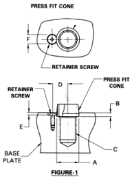
1. Position holes, drill and tap per chart
"C" measurement.
2. Drill and ream hole for Press Fit Cone
per chart "A" and "B" measurement (Figure-1).
3. Press cone into reamed hole using standard
hex bolt and nut. Hold bolt stationary and
turn hex nut to press cone into position.
NOTES:
It is recommended that a 8-32 x 1/2" P-Truss
retainer screw be used with a 3/4" and larger
Full-Contact Clamp (Refer to figure-1 and
chart "G").
An adhesive or an Epoxy may be used in place
of the retaining screw.
| |
1/2" |
3/4" |
1" |
| (A) REAMED HOLE DIAMETER |
.490 |
.740 |
.950 |
| (B) REAMED HOLE DEPTH |
.150 |
.160 |
.160 |
| (C) TAPPED HOLE |
3/8-16 |
1/2-13 |
3/4-10 |
| (D) RETAINER CENTER LINE |
- |
.525 |
.630 |
| (E) RETAINER SCREW COUNTER BORE |
- |
.110 |
.110 |
| (F) RETAINER SCREW HEAD DIAMETER |
- |
.380 |
.380 |
| (G) RETAINER SCREW |
- |
8-32X1/2 P-TRUSS |
8-32X1/2 P-TRUSS |
| (H) FIXTURE PLATE HOLE DIAMETER |
.495 - .515 |
.745 - .765 |
.995 - 1.015 |
| OPTIONAL HEADLINER BUSHING |
HL 48-12 |
HL 64-16 |
HL 88-16 |
| MAX. LOAD |
4200 LBS. |
7500 LBS. |
1100 LBS. |


FIXTURE
PLATE
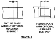
1. Position hole to match Base Plate
Hole Locations. Drill and ream to dimensions
as
required in chart "H" measurement.
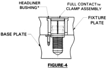
2. If optional liner bushing is used, drill
and ream per bushing manufacturer recommend

 |